Click to view our Accessibility Statement or contact us with accessibility-related questions


Showing 1 of 461 conversations about:

zcmckenna
15
Nov 2, 2020
bookmark_border
CTB1
3
Nov 2, 2020
bookmark_border
zcmckennaMuch thanks for posting!
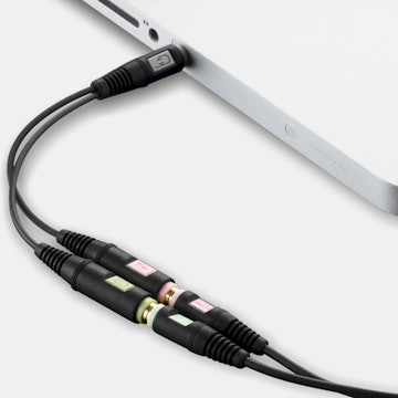
Also, for those who may not have the desire or tools to open up the unit:
- Cut & then splice a short headphone cable (https://www.amazon.com/gp/product/B07DK4LZ5F/ref=ppx_yo_dt_b_search_asin_title?ie=UTF8&psc=1 ) in the middle reversing L&R
- Reverse RCA outputs as you plug cables L&R for output
I know this is obvious and not as aesthetic, but it’s simple, so thought I’d mention it.
(Edited)
Related Products


Drop Refurbished
Like-new products you can trustDrop Rewards
Get $5 for every 500 points you earn! Learn more
Drop Keyboard Club
Become a member and expand your keycap collectionCollaborate With Us
For Brands & DesignersFollow Drop
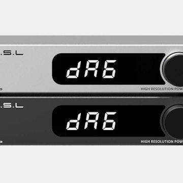
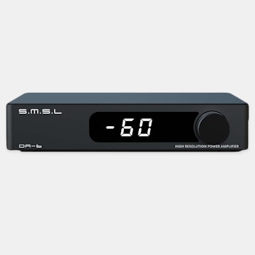
Before you start: Disclaimer: you could damage or kill your DAC/amp when opening it. Use care when performing this fix and make sure discharge any static electricity on your body on a light switch or another grounded point before you start. Also, make sure to check that you L/R channels are incorrect before you attempt the fix, there are many ways to check this (Many OS have a built in way to test this in sound settings). Fixing the Amp: Step 1: Using the Torx T10 screwdriver remove larger screw (in blue) above the RCA ports and using the T6 screwdriver remove the 4 screws (in red) on the rear of the case.