Click to view our Accessibility Statement or contact us with accessibility-related questions


SETTING UP YOUR CARINA

search
close
Sort by: Newest
keyboard_arrow_down
pomjellykeycaps
0
Oct 7, 2022
can i use prebuilt stabilizers? building the stabilizers myself seems intimidating.

artificialash
0
Sep 25, 2021
Hello, I have installed all of the switches and they all work except for my Right ALT key. I have taken the switch out, checked for bent pins (no bent pins), replaced the switch, repeated the process a few times. Are there any suggestions as to what I should do?
(Edited)
EnronMxela
3
Oct 6, 2021
artificialashBy default, the right ALT key is actually the modifier key to switch layers
NCW1248
0
Oct 19, 2021
ismynameuzihey bro i had the exact same problem, open the configurator highlight all of the leds, select the options on the side and do the rest. if you want more detail add my discord @N.C.W#1484

schweaty
6
May 3, 2021
hey guys, i'm trying to flash the firmware on my carina with a custom configurator file but my board keeps getting stuck after entering DFU mode. I hear the windows chime like a device is disconnected/connected and the led on the bottom of the board will blink orange once or twice then stay solid orange. It'd stay that way till i reconnect the board and all is normal again. I've tried different usb ports (2.0 and 3.0) and different usb type c cables but nothing seems to work. guys have any ideas?
thanks!
edit: nvm, got it all sorted.
(Edited)
ahgc
2
Jan 26, 2021
hey guys, ive been having the drop carina keyboard for about a month or two and it is wonderful. however, i recently built a new pc nd now the keyboard isnt recognized....windows says theres a driver error....any ideas on how to fix?
bioniclady
0
Mar 23, 2021
ahgcUninstall the device and then plug it back in. That should force Windows to reinstall the drivers.
Exlipse
2
Dec 14, 2020
I have tried doing step 3, however my board only has a continuous orange light flashing. I have tried unplugging and plugging back in, and changing to many different USB ports, but to no avail. Could someone help?

edanirac
3
Dec 6, 2020
Can anyone help me configure the keyboard?
I've downloaded all the necessary files for the mdloader.. however when I try to execute "chmod u+x mdloader_mac" it says no such file or directory, even though I've changed the directory to a folder containing everything.
I've tried to bypass the need to execute using "./mdloader_mac --first --download "my_file_name" --restart", however it still says no such file or directory.
I'm new to this so any help would be awesome!
Thanks!
Edit: It started working once I downloaded the default .bin file for the keyboard and put in the same folder! :)
(Edited)
balooberry
3
Dec 1, 2020
Just attempted to configure my LEDs through the process here: https://drop.com/talk/9382/how-to-configure-your-ctrl-keyboard/2486201
Everything was successful, but now my keyboard refuses to turn back on. I get a flashing orange LED when I have the USB plugged in, but nothing else. No LEDs, no key inputs, nada.
I tried to put the default configuration back on and once again it was also successful, but the keyboard still isn't responsive.
edit: I reckon it helps if you use the correct firmware. I have solved my issue, just trying to see if I can change the LEDs still, gave me a parse error the first time.
edit2: second problem solved, all good! keyboards' working dandily and it's as blue as I want it to be.
(Edited)
RoseSelkie
0
Dec 2, 2020
balooberryHow did you manage to get it to work? I downloaded the carina firmware and did the command in powershell following the directions, but I'm getting the orange light vs actually seeing my keyboard be blue.
Edit: no joke, unplugging it and plugging it back in worked.
(Edited)

DetectiveSocks
66
Dec 9, 2020
balooberryI got the same problem too! How did you fix your problem? I tried using Drop’s configurator and when I tried to compile, it kept stalling and wouldn’t give me a prompt to download. So I just to QMK and download the CTRL compile.
Showing 23 of 31
PRODUCTS YOU MAY LIKE
Trending Posts in Mechanical Keyboards

RealRage_TV
software?
Hi I'm new to Drop and i just received my Keyboard i have been waiting for months for by Drop x MTN Dew x Borderlands movie and didn't know if there was a software like Logitech's for the keyboards. if anyone could help please let me know
Nov 20, 2024

jdsvdropper
Drop ENTER keyboard with DCX Sleeper Mac variants and Rocky Bird
Black Drop ENTER keyboard with DCX Sleeper Mac variants for the Option and Command keys, and Rocky Bird red and black DCX keycaps.
Nov 19, 2024
AngryTank
Favorite Artisans
COME FORTH SHENRON!
Purple, Dragon Balls, and Seta! What more does a simple man need?
Nov 17, 2024
InsufferablePedant
ZealPC Aqua Zilents
Please ignore the filthy keyboard, it's been on a shelf for a minute.
Nov 15, 2024

Neekolas714
Kicks & Keebs
Alpha Bravo Smoke
Finally finished my Keychron V5. Smooth, beautiful and stylish. What else could there be?
Nov 13, 2024

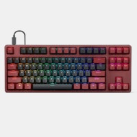

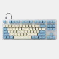


Step 2: Install PCBA & Standoffs Inspect the PCBA for visible issues. With the side of the PCBA that has surface mounted components facing down, angle and gently lower the USB-C ports into the two cutouts before lowering the rest of the circuit board into the acrylic case.
Step 3: Test Basic Functionality Plug in the keyboard and check if everything is working. Every LED should be lit. Be sure to check the per-switch LEDs as well as the underglow LEDs.
Step 4: Assemble Stabilizers You should have 5 wires (4 short and 1 long), 10 stabilizer inserts and 10 stabilizer housings. If you prefer quieter sounding stabilizers you can lube or grease them during assembly.
- Assembling the Inserts and Housings
Take one insert and drop it into a housing. There is only one correct orientation. If the insert does not seem to fit, remove it, rotate it 180 degrees and try again.- Add Stabilizer Wire
It goes through the opening on the housing and through the bottom hole on the insert. Align the two parts, insert the bar, and it should look like this.- Install Stabilizers on the plate
Rotate each stabilizer assembly so the bar faces towards the bottom in U shape. Drop the bar through the cutout, pull down until both stabilizer ends are seated on the plate, then push the opposite end into place. They will clip into the plate. Install the other four in the same way.Step 5: Install Switch Plate Before installing the switch plate, we will first add switches to the four corners of the plate. This is an important step to align the plate with the circuit board and prevent damage during assembly. Before placing each switch you want to check the underside and see if the pins are straight. If bent, you can use your fingers to straighten them but it's best to use another one instead.
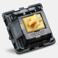
Step 6: Add Switches Check each switch for straight pins (orthogonal to the bottom of the switch). If they are slightly angled, you can gently straighten them with your fingers.
- Check Switches & Troubleshooting
Once all the switches are in, check for functionality. Plug your USB-C cable into your keyboard and computer. You should see all your keys lighting up. Next check that each switch is working. Navigate to keyboardtester.com, launch the tester and check that each switch outputs correctly when pressed. Note that pressing the function key by itself will not show anything. You’ll need a combo like fn + 1 (outputs F1) to see if the key is working. If there’s a problem, press the switch down firmly to make sure it's fully seated. If you still have trouble, remove it using a switch puller and check for bent pins. Place the tips into these grooved slots above and below the switch. Squeeze firmly to depress the tabs, and pull straight up to remove the switch.Step 7: Add Keycaps Lastly, add your desired keycaps.