Click to view our Accessibility Statement or contact us with accessibility-related questions


PRODUCTS YOU MAY LIKE
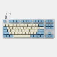

Trending Posts in Mechanical Keyboards
NewmanDA9901
LOTR Keyboard with Hardcore keycaps?
Hello. Is there a way to get the DROP + THE LORD OF THE RINGS™ BLACK SPEECH KEYBOARD with only the HARDCORE BASE KIT keys? Without the English letters on it. I really want one but it would be awesome if it came with the hardcore kit installed. Thanks in advance!
May 2, 2024


mabyen
Battlestations
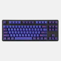
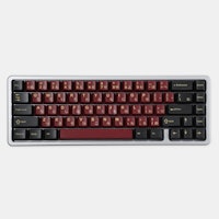
Black Speech keyboard
Looks and feels good and mechanical sound is great!
May 1, 2024

dovenyi
What is SpaceFN and why you should give it a try
The SpaceFN concept - setting up your space key as a layer switch when held - is probably one of the most useful tweaks in the keyboard hobby. Let me explain how it works. My SpaceFN article on kbd.news made some rounds recently - quite surprisingly given the age of this concept. This piece you're reading is a condensed version of the full post. If you're left with unanswered questions, you'll most likely find the info you're looking for in the original write-up. On my imaginary top list of the most useful keyboard features, tweaks and hacks, SpaceFN would deserve a podium finish for sure. But what makes it so special? In short: SpaceFN is easy to implement, easy to learn, costs nothing, can be used with any keyboard, and can improve your productivity instantly. I will list its benefits below, but can state right at this point that the SpaceFN concept, setting up your space key as a layer switch when held, is clearly one of the most useful tweaks in the keyboard hobby....
Apr 30, 2024
Ike4948
Silent Holy Panda X?
I ordered some Holy Panda X switches, and I fell in love with them. They are a joy to type on. There's just one problem. The place that I use my keyboard to type the most is obviously at work, which is a problem if I want to use the Holy Panda X in the office around a whole bunch of people. I really don't want to torture my coworkers with the clack of these switches. I'd rather they still liked me. The good news is that, for me, the actuation of the Holy Panda X is the best part. I could take or leave the sound it makes; even if it is fantastic. Which leads me to my conundrum: is there another "silent" switch that feels similar to the Holy Panda X? Is there a piece I can remove from the Holy Panda X that would allow me to make them silent? Or am I going to have to wait and see if Drop will drop a Silent Holy Panda X for the in-office mech community?
Apr 29, 2024


DaveKaretnyk
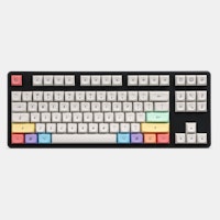
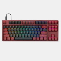
Mode Tempo with Red Samurai
Mode Tempo (60%) with GMK Red Samurai & Mode Lotus keycaps
Apr 25, 2024
Drop Refurbished
Like-new products you can trustDrop Rewards
Get $5 for every 500 points you earn! Learn more
Drop Keyboard Club
Become a member and expand your keycap collectionCollaborate With Us
For Brands & DesignersFollow Drop
Fuse is placed in the circuit to cut of somewhere between 0.5 to 1.1 ampere.
You can find the pin layout of the keyswitches on github.com/qmk/qmk_firmware/keyboards/knops/mini/ (I am not sure if this link is completely correct, currently on mobile)
The link is https://github.com/qmk/qmk_firmware/tree/master/keyboards/knops/mini ;) I much prefer reading a schematic over digging the info out of source code, hence my asking. Esp. since it's more than just the switches -- LED's, speaker, HWB (going to replace the bootloader), to name a few of the top of my head.
Edit: got it working after taking it apart and measuring some continuity -- turns out that the sequence "Miso, Vcc, SCK, Mosi, Reset, Ground" is from right to left when looking at the pins. :/
Each keyswitch has a led as well. These are connected to a gpio of the 32u4 on one side and ground on the other
The three layerleds are a bit different regarding to keyswitch leds in that the first and third is connected to a gpio pin on one side and Vcc on the other. The second layer led is connected to a gpio pin and ground. This has to do with arduino compatibility, layerled 1 and 3 replace the RX and TX leds you will normally find on the Arduino Leonardo.
The speaker is connected to two pins, so that you can make multiple tones at the same time.
pins per keyswitch: keyswitch 1: PF7 keyswitch 2: PF6 keyswitch 3: PF5 keyswitch 4: PF4 keyswitch 5: PF1 keyswitch 6: PF0
pins per led (for keyswitches): led 1: PD7 led 2: PC7 led 3: PD4 led 4: PE6 led 5: PB4 led 6: PD6
pins per led (for layer indication): led 1: PD5 (to Vcc) led 2: PB6 (to Gnd) led 3: PB0 (to Vcc)
pins for speaker: one side: PC6 other side: PB5